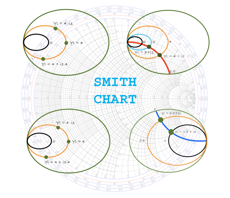
I have not been able to find documentation on the formula used to construct this part of the Smith Chart. Values on the inner two circles of the Smith Chart (where the ray from the origin through the point Z1/Z0 cuts the circles). The Smith chart is usually normalized to a terminating. You’ll not learn the mysteries of the Smith Chart, or those sophisticated formula and special usages of this great chart here. We’ll discuss the Smith Chart in this sequence and start with the very basic knowledge of this important tool that all RF people should learn and use. Tried and true, the Smith chart is still the basic tool. Smith Charts-Basics, Parameters, Equations, and Plots. This experiment will be helpful in learning following topics: Realization of Smith chart and the basics of drawing a Smith chart. From this experiment we will learn to use the Smith chart for transmission-line calculations. What is Smith chart and how does it work Smith chart was invented by Phillip Smith in 1939 as a graph-based method of simplifying the complex math used to describe the characteristics of RF/microwave components, and solve a variety of RF problems.


A sample matching network is designed at 60 MHz using graphical methods. This experiment gives an introduction to Smith chart and its application for the unknown impedance measurement. The Smith Chart is a fantastic tool for visualizing the impedance of a transmission line and antenna system as a function of frequency. Examples are shown plotting reflection coefficients, impedances and admittances. We didnt try to put every last line on the chart, most times you use a Smith Chart you are more interested in approximate. Its just a matter of creating equations for semi-circles, something any nerd can do. New for January 2008 Weve created a Smith chart within Excel. Measure the phase angle of the complex number T (when both complex numbers are written in polar form).īut when I substitute test values for Z1 and Z0, and compute the corresponding phase angles for Gamma and T, they do not coincide with the 3: Illustration of the transformation of basic shapes from the Z to the plane. of 16 WIRELESS, RF, AND CABLE Application Note 742: Impedance Matching and the Smith Chart: The Fundamentals Tutorial on RF impedance matching using the Smith Chart. Click here to go to our main page on Smith Charts. The Angle of Reflection Coefficient should measure the phase angle of the complex number Gamma, and the Angle of Transmission Coefficient should It seems that the latter is rarely used, and the values on the chart don't make sense to me. The inner two circles on the traditional Smith Chart are supposed to measure "Angle of Reflection Coefficient in Degrees" (Gamma) and "Angle of Transmission Coefficient in Degrees" (T).


 0 kommentar(er)
